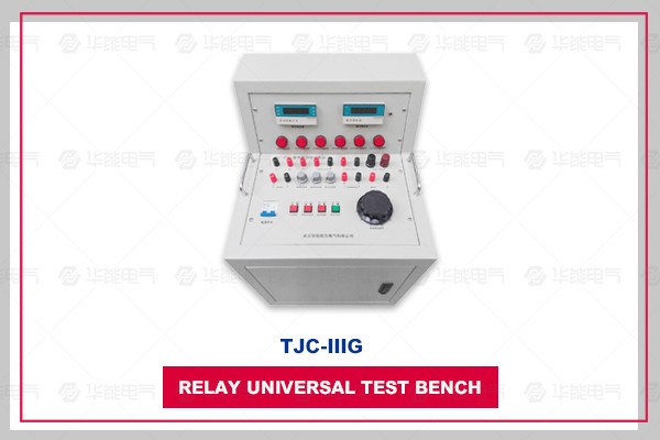
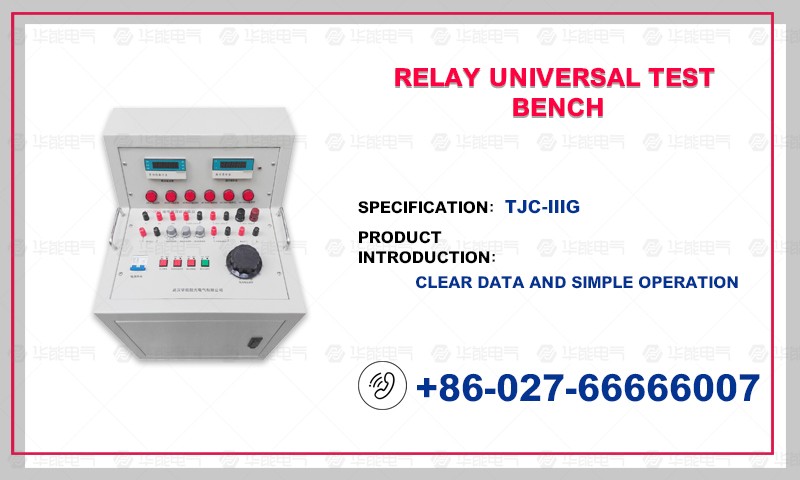
Panel Layout and Function Description
Panel Layout:
Functional description:
(1), J1, J2, J3, J4, J5 are AC, DC power supply and its fixed value output terminals, as shown in the panel.
(2) X1 is the current and voltage value display (display start value, return value and rated value), X2 digital millisecond watch.
(3) S1 power socket, S2 power switch.
(4) T1 power supply output selection knob, T2 fixed value output selection knob, T3 contact state selection knob (which means that the action value and return value can be judged by lamp, I means the constant open contact power-on delay, II means the constant open contact power-off delay, III means the normal closed contact power-on delay, IV means the constant closed contact power-off delay.) T4 power output size adjustment knob.
(5) Contact: The terminal of the contacts of the verified relay. Note: When measuring the relay operation time, the relay contacts can not have external power supply, and can not be short-circuited with J1, J2, J3, J4 and J5 of this instrument.
(6) Z: Represents the type of power output.
(7) Action instructions: instructions when contacts act. (If contacts are frequently opened, the indicator lights will be turned on after the action; if contacts are normally closed, the indicator lights will be turned on and off after the action.)
(8) Synchronization: Controlling the on-off of the output voltage or current, and conducting impact test of rated value of relay.
(9) Fixed value: Fixed value output switch.
(10) Reset: Zero the millisecond watch.
(11) Closing: The switch-on signal emitter of reclosing relay.