It is suitable for AC withstand voltage test of 110 kV cable, AC withstand voltage test of transformer under 120 MVA/110 kV, and AC withstand voltage test of 110 kV bus and GIS.
Regarding product purchases, technical maintenance, and other services, please feel free to call:400-8828-058
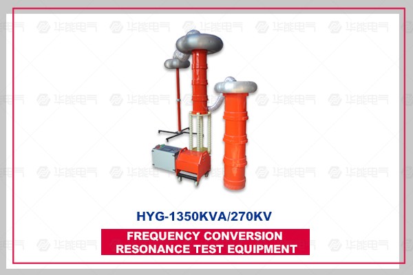
1. It meets the AC withstand voltage test of 400 mm 2,110 kV cable with length of 2 km, capacitance less than 0.312 uF, test frequency 30-300 Hz and test voltage U less than 128 kV.
2. It satisfies the AC withstand voltage test of transformers below 120 MVA/110 kV, with capacitance less than 0.025 uF, test frequency 45-65 Hz and test voltage U less than 160 kV.
3. The AC withstand voltage test of GIS meets the requirement of 110 kV bus. The test frequency is 30-300 Hz, and the test voltage U is less than 265 kV.
I. Technical parameters of the system
Rated output voltage: 0-270 kV
Resonant voltage waveform: sine wave, waveform distortion rate less than 1.0%.
Maximum test current; 5A
Maximum test capacity: 1350 kVA
Output frequency: 30-300 Hz
Working time: 60 minutes continuous working time under full power output
Quality factors: 30-90
Input power supply: three-phase 380V + 10%, 50Hz
Ambient temperature: - 15 + 40.
Relative humidity: <90RH%, no condensation condition
Altitude: <3500m
Noise: <50dB
II. Workingenvironment
Ambient temperature: - 150C - 400C;
Relative humidity: <90% RH;
Altitude: <3500 M.
III. Systematic Implementation Standards
GB50150-2006 "Standard for Handover Test of Electrical Equipment in Electrical Equipment Installation Engineering" DL/T849.6-2004 "General Technical Conditions for Special Testing Instruments for Electrical Equipment Part 6: High Voltage Resonance Testing Devices"
JB/T9641-1999 "Test Transformer"
GB10229 Reactor
GB/T.311-1997 Insulation and Coordination of High Voltage Transmission and Distribution Equipment
DL/T846-2004 General Technical Conditions for High Voltage Testing Equipment
GB4793-1984 Safety Requirements for Electronic Measuring Instruments
GB2900 Electrical Terminology
GB4208 "Shell Protection Level"
GB191 "Packaging, Storage and Transportation Marks"
GB/T16927-1997 High Voltage Test Technology
IV. DETERMINATION OF DEVICE CAPACITY
It meets the AC withstand voltage test of 400 mm 2,110 kV cable, with a length of 2 km, a capacitance of less than 0.312uF, a test frequency of 30-300 Hz and a test voltage of U less than 128 kV.
Frequency 35 Hz
Test current I = 2 pi fCU test = 2 pi ×35 ×0.312 ×10-6 ×128 ×103 = 8.7A
Corresponding inductance of reactor L=1/2C=66H
When two-section reactor is designed and used in parallel, the parameters of single-section reactor are 675KA/135KA/5A/132H, and the total capacity of the device is 1350KA.
Verification: 1. To meet the AC withstand voltage test of transformers below 120 MVA/110 kV, the capacitance is less than 0.025 uF, the test frequency is 45-65 Hz, and the test voltage is less than 160 kV.
The inductance is L=132*2=264H when the reactor is connected in series.
The test frequency f=1/2 pi_LC=1/(2×3.14×264×0.025×10-6)=61.9 Hz.
The test current I = 2 pi fCU = 2 pi x 61.9 x 0.025 x 10-6 x 160 x 103 = 1.5A.
CONCLUSION: The capacity of the device is set at 1350KA/270KV/45KV, which consists of two sections of reactor and 675KA/135KV/5A/132H single section. The combination of reactors can meet the test requirements of the above-mentioned subjects.
V. Use Relational Table in Testing
Equipment combination
Trial product
Reactor 675KA/135KV
Two quarter
Output Selection of Excitation Transformer
Satisfies 110 kV/400 mm2 cable, (test voltage < 128 kV, test time 60 min)
Length less than 1000M
Using a Reactor Section in Series
5kV
Length 1000-2000m
Two Sections Parallel Connection Using Reactors
5kV
Transformers below 1120MVA/110kV are satisfied. (Test voltage 160 kV, test time 1 min)
Using Reactor Two Sections in Series
5kV
Satisfies 110 kV bus, GIS, (test voltage < 265 kV, test time 1 min)
Using Reactor Two Sections in Series
15kV
Technical Specification and Performance of Main Components
6.1 Variable Frequency Power Supply Control Box HYG-50KA/0.4KV 1
6.1.1 Technical parameters
6.1.1.1 Input power supply: three-phase 380V + 5%, 50Hz.
6.1.1.2 Output voltage and current: 0-400V, maximum current 125A.
6.1.1.3 Output frequency: 30-300 Hz, frequency regulation fineness 0.1 Hz, instability less than 0.05%.
6.1.1.4 Rated Output Capacity: 50KA
6.1.1.5 Shape size and weight: 600 x 600 x 1200 mm; 150 kg
6.1.2 Performance Characteristics
6.1.2.1 parameter setting: test voltage, withstand voltage time, test mode, test current, and other parameters can be set or selected.
6.1.2.2 Test mode: manual test mode and automatic test mode
A. Manual test mode: with boost, tuning (including manual and automatic), step-down (manual and automatic) functions.
B. Automatic test mode: After entering the test state, the main circuit is automatically tuned, boosted, timed, lowered, cut off and transferred to the test result interface.
6.1.2.3 Protection function and its information prompt: with high voltage over-voltage, low voltage over-current protection, as well as detuning protection, zero, discharge protection and other multiple protection functions.
6.1.2.4 Data storage function: test results preservation, review and so on.
A. Test results: After manual or automatic test, the detailed parameters of the test can be displayed in the test results interface. The parameters can be stored in memory, which is a non-volatile memory and can save 200 test records.
B. Data query: The saved experimental data can be displayed on the screen.
6.1.2.5 Automatic Voltage Stabilization Function: According to the set test voltage or manual boost results, the system automatically tracks and maintains a stable test voltage, and the voltage stability can reach 1%.
6.1.2.6 FM range setting: FM range can be set to 20-300 Hz.
6.1.2.7 Overvoltage Protection Function: Software Overvoltage Protection Value, abundant High-voltage Overvoltage Protection Function, more safety, effective protection of human beings, equipment and test products.
6.1.2.8 Over-current protection: Over-current protection value can be set manually; when the output current of the whole set of devices reaches the protection setting value, the whole set of devices can be automatically removed.
6.1.2.9 Breakdown Protection: It has the function of discharge or flashover protection. When flashover occurs on the high voltage side, the whole set of device is automatically removed. It will not cause harm to test equipment and human body, and the electronic components in the variable frequency power supply will not break down.
6.1.2.10 Power-off Protection: After the test power supply is cut off, the device can be quickly protected.
6.2 Excitation Transformer JLB-50KA/1.5KV/3KV/5KV/15KV/0.4KV
Configuration features: will be high power
Taking full advantage of our company's advantages in electronic measurement technology and electromagnetic compatibility, we fully independently develop, design and produce all components of the equipment, including frequency conversion power supply, excitation transformer, castable high-voltage reactor and high-precision capacitor divider.
It has manual/automatic mode, large screen display, test parameter setting, and automatic timing and operation prompt function.
It has many protection functions, such as over-voltage, over-current protection, discharge protection, detuning protection, etc.


武汉华能阳光销售经理

