The tester is mainly designed and manufactured for AC withstand voltage and partial discharge measurement of 150 kV transformer, circuit breaker and 150 kV/31500 kVA main transformer.
Regarding product purchases, technical maintenance, and other services, please feel free to call:400-8828-058
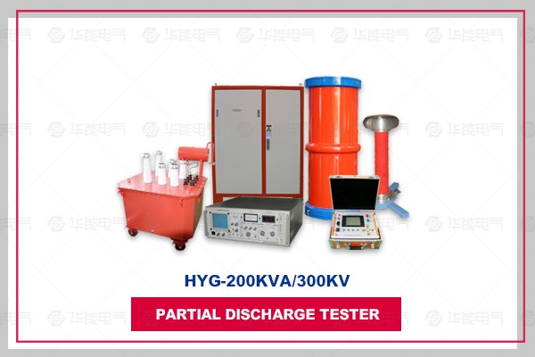
The tester is mainly designed and manufactured for the AC withstand voltage and partial discharge measurement test of 150 kV transformer, circuit breaker and 150 kV/31500 kVA main transformer. Reactors are designed separately, which not only meets the requirements of high voltage and low current equipment test conditions, but also has a wide scope of application. High voltage test departments and power installation and repair engineering units are ideal voltage withstanding test equipment.
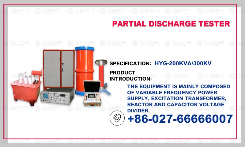
The device is mainly composed of frequency conversion control power supply, excitation transformer, reactor, capacitor voltage divider, partial discharge tester and so on.
300 kV - - - 150 kV transformer, circuit breaker AC withstand voltage and partial discharge test;
2 * 20kV - - - meet the induction withstand voltage and partial discharge test of 150kV main transformer.
2. Output voltage waveform distortion rate: <1.0%
3. Continuous working hours allowed: 180 minutes of one-time work under rated conditions;
4. Device's own quality factor: Q > 30 (f = 50Hz)
5. Output waveform of device: sine wave
6. Input power supply: three-phase 380V
7. Frequency regulation range: 30Hz-300Hz
8. Measurement accuracy of the system: 1.5%
9. The device has protective functions such as over-voltage, over-current and zero-position starting.
(3) Equipment conforms to standards
Standard for Handover Test of Electrical Equipment in Electrical Installation Engineering GB50150-2006
High Voltage Resonance Test Device DL/T 849.6-2004
Reactor GB10229.88
Regulations for Preventive Testing of Electric Power Equipment DL/T596-1996
"Coupled Capacitors and Capacitor Voltage Dividers" IEC 358 (1990)
(4) Description of main equipment configuration and technical parameters
1. Frequency Conversion Power Supply
2. High Voltage Reactors (Two Sets)
Rated operating voltage: 150 kV
Rated working current: 1A
Rated inductance: 420H
Continuous working hours: 15 minutes
Temperature rise: less than 65K
Working frequency: 50-300 Hz
3. Excitation transformer (one)
Rated capacity: 200 kVA
Input voltage: 350V/400V
Output voltage: 2*5/20
Output current: 20/5A
4. Voltage divider 1 without partial discharge
Self-capacitance: 300 pF
Rated voltage: 60 kV
Working frequency: 30-300 Hz
Partial discharge: <10pC;
Partial pressure ratio: 1000:1
Uncertainty: 1.5%
Rated voltage: 60kV/300pF
5. Voltage divider without partial discharge 2
Self-capacitance: 400 pF
Rated voltage: 300 kV
Working frequency: 30-300 Hz
Partial discharge: <10pC;
Partial pressure ratio: 4000:1
Uncertainty: 1.5%
Rated voltage: 300kV/400pF
6. Test Line Set
1. The required power supply capacity is greatly reduced. Series resonant power supply generates high voltage and large current by resonant reactor and capacitor resonance. In the whole system, the power supply only needs to provide the active power consumption part of the system. Therefore, the power required for the test is only 1/Q of the test capacity.
2. The weight and volume of the equipment are greatly reduced. In series resonant power supply, not only the heavy high-power voltage regulator and common high-power test transformer are omitted, but also the resonant excitation power supply only needs 1/Q of the test capacity, which greatly reduces the weight and volume of the system, generally 1/10 of the ordinary test equipment.
3. Improving the waveform of output voltage. Resonant power supply is a resonant filter circuit, which can improve the waveform distortion of the output voltage, obtain good sinusoidal waveform, and effectively prevent the wrong breakdown of the sample by harmonic peak.
4. Prevent large short circuit current from burning fault points. In the series resonance state, when the insulation weakness of the sample is broken down, the circuit immediately detuning and the loop current rapidly drops to 1/Q of the normal test current. When the shunt resonance or test transformer is used for withstand voltage test, the breakdown current increases tens of times immediately. Compared with the two methods, the short circuit current is hundreds of times different from the breakdown current. Therefore, series resonance can effectively find the insulation weakness, and there is no big short-circuit current burn fault point.
5. There will be no recovery overvoltage. When the sample breaks down, because of the loss of resonance condition, the high voltage also disappears immediately, the arc extinguishes immediately, and the process of rebuilding the recovery voltage is very long. It is easy to disconnect the power supply before reaching the flashover voltage again. This process of voltage recovery is an intermittent oscillation process of energy accumulation, and it has a long process without any recovery overvoltage.


武汉华能阳光销售经理

