The HYG-2000 Bureau Test Instrument is a four-channel product. It uses a large screen display screen with high frequency elliptical scanning(intake power & lt; 1 Volt), the amplifier system has a large dynamic range, an auxiliary zero standard system, a linear, logarithmic dual-function pointer header and a digital header, which can display the discharge of discharge pulses at the same time.
Regarding product purchases, technical maintenance, and other services, please feel free to call:400-8828-058
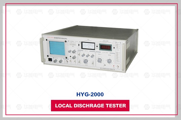
The HYG-2000 Bureau Test Instrument is a four-channel product. It uses a large screen display screen with high frequency elliptical scanning(intake power & lt; 1 Volt), the amplifier system has a large dynamic range, an auxiliary zero standard system, a linear, logarithmic dual-function pointer header and a digital header, which can display the discharge of discharge pulses at the same time.
The power part of HYG-2000 release instrument is added to AC filter, which can effectively filter out the harmonic interference of the power supply; The new EMI design is adopted in the circuit, and the impact protection at the new increase can effectively improve the instrument's anti-interference ability and make the partial discharge reading more accurate; The display unit enhances the anode voltage, improves the focusing and brightness performance, and makes the partial discharge waveform clearer.
The HYG-2000 locator has three display functions. The localizer cooperates with the measurement impedance and can display the waveform synchronized with the test power supply on the oscilloscope screen. When adjusting the gain, the panel should have a light indicator. The product also adds a Humanized design that synchronizes the panel to display the currently observed channel number digitally.
The HYG-2000 release instrument is a powerful auxiliary tool for the study and development of new Gaodianya electrician products and the improvement of product quality. It is also an effective test instrument for judging whether the equipment is working properly on the spot. The instrument is used in conjunction with the HYG-9 or HYG-10 correction pulse generator and is particularly suitable for the power sector, production manufacturers and scientific research units.
Key words: four channels, current channel number display, variable band measurement function, EMI design.
1, adopt modular, independent four-channel design, each channel has good consistency.
2, through the software processing real-time display of the current observation channel number, making the operation more intuitive and understandable.
3, integrated filter design, covering 10 kHz ~ 300 kHz, meeting the IEC 60270 standard and GB7354 standard requirements.
4, the addition of AC filter processing and multiple impact protection can effectively filter out the harmonic interference of the power supply, improve the instrument's anti-interference ability, and make the partial discharge reading more accurate.
1, measurement channel: four channels
2, testable capacity range 6pF ~ 250 μF
3, detection sensitivity and allowed current(see table 1)
Input Form Meta Serial Number |
Tuned capacitance range |
Sensitivity(pC) (unbalanced circuit) |
Allow current valid value | |
| Unbalanced circuit |
Balance circuit | |||
1 |
0~25~100pF |
0.02 |
30mA |
0.25A |
2 |
25~100~400pF |
0.04 |
50mA |
0.5A |
3 |
100~400~1500pF |
0.06 |
120mA |
1A |
4 |
400~1500~6000pF |
0.1 |
0.25A |
2A |
5 |
1500~6000~25000pF |
0.2 |
0.5A |
4A |
6 |
0.006~0.025~0.1μF |
0.3 |
1A |
8A |
7 |
0.025~0.1~0.4μF |
0.5 |
2A |
15A |
8 |
0.1~0.4~1.5μF |
1 |
4A |
30A |
9 |
0.4~1.5~6.0μF |
1.5 |
8A |
60A |
10 |
1.5~6.0~25μF |
2.5 |
15A |
120A |
11 |
6.0~25~60μF |
5 |
25A |
200A |
12 |
25~60~250μF |
10 |
50A |
300A |
7R |
resistance | 0.5 |
2A |
15A |
4, elliptical scanning base
(1) Frequency 50(inner), 100, 150, 200, 400 Hz(internal and external synchronization function)
(2) Rotation: in the first gear of 30 °, it can rotate 360 °
(3) Working methods: Elliptic-extension-straight lines
(4) At high frequencies, the base ellipse can be adjusted to normal size according to the input voltage(10 to 250 V), and its intake power is & lt; 1 Volt with automatic overload protection
5, display unit
Adopt 124 × 104mm2 rectangular waveguide with brightness and focus knob
6, variable-band amplifier
(1) 3dB low frequency fL: 10, 20, 40 kHz optional
(2) 3dB high frequency fH: 80, 200, 300 kHz optional
(3) Gain adjustment, gain difference between files 20 ± 1 dB, fine range & GT; 20dB
(4) Asymmetric positive and negative pulse response & lt; 1dB
7, time window
(1) Window width: adjustable, 15 ° ~ 150 ° at 50Hz
(2) Window position: Each window can rotate 0 ° ~ 170 °
(3) Two time windows can be opened separately or at the same time
8, Pulse peak table(pointer display and digital display)
(1) Linear scale pointer header 0-100
(2) Logarithmic scale pointer header 0-10-100
(3) Digital Header: Show 0-100 with 3 and a half LED digital tables
(4) Linear error measurement of discharge power & lt; ± 10 %
9, zero standard system
(1) The zero mark of the internal zero standard generator has phase resolution and can be rotated 0 to 180 ° to match the polarity of the true zero position generated by the voltage resistance R
(2) Zero marks are consistent with all elliptical scanning frequencies
10, power voltage
AC 220V(50Hz ± 10 %)
11, use environment
Environmental temperature -5 ~ +45 °C, relative humidity ≤ 85 % RH
When the test CX produces a partial discharge at the test voltage, a pulse current is generated by the coupled capacitor Ck, and the pulse signal is picked up by the input unit. After the low noise Preamplifier amplifies, the filter amplifier selects the desired frequency band and the main amplifier amplifies(to the desired amplitude), a visible discharge pulse is generated on the elliptical scanning baseline of the display screen, and the pulse peak table is also sent. Show its peak value. The time window unit is a period of time for selecting the pulse peak table in each cycle of the test voltage; During this period of work, the corresponding display area of the display screen is highlighted. It can avoid fixed phase interference. This is a conventional discharge test method.
Using HYG type correction pulse generator to inject the test CX -- When the power is known, adjusting the amplifier's fine-tuning knob so that the value displayed by the discharge meter is the same as the injected power, the measured power can be read directly on the table during the voltage test. No calculation is required. Very convenient.
The test voltmeter produces a test voltage over zero sign signal through the resistance R of the voltmeter. The zero mark pulse can be displayed on the display screen. The test voltage can be displayed by the KV meter.


武汉华能阳光销售经理

