HYG high pressure withstand tester is designed and produced according to DL/T848.2-2004 industry standard, suitable for power system, industrial and mining enterprises, scientific research departments, etc. for high voltage electrical equipment, electrical components, insulating materials under power frequency high pressure Insulation strength test Our company can customize any parameter non-standard pressure-resistant products and equipment!
Regarding product purchases, technical maintenance, and other services, please feel free to call:400-8828-058
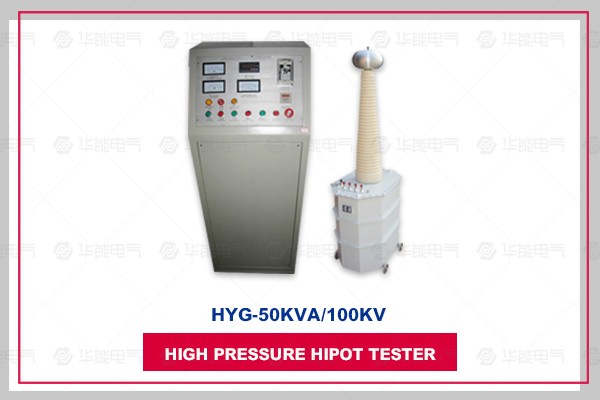
The HYG high pressure withstand test is designed and manufactured according to the DL/T848.2-2004 industry standard. The complete set consists of a high-voltage test transformer and a control box (table). The control box (stage) consists of an integrated device consisting of a voltage regulator, measurement, control and protection. It is applicable to the insulation strength test of power high voltage electrical equipment, electrical components and insulating materials under power frequency and high voltage for power systems, industrial and mining enterprises and scientific research departments. The HYG high pressure withstand tester is designed and manufactured according to the DL/T848.2-2004 industry standard. The complete set of equipment consists of HYG high-voltage test transformer and control box (table). The control box (stage) consists of an integrated device consisting of voltage regulator, measurement, control and protection. It is applicable to the insulation strength test of power high voltage electrical equipment, electrical components and insulating materials under power frequency and high voltage for power systems, industrial and mining enterprises and scientific research departments.
The products are divided into two types: integrated devices and split devices.
Test transformer capacity selection
The formula for determining the nominal test transformer capacity Pn: Pn=kVn 2ωCt×10-9
Where: Pn - nominal test transformer capacity (kVA)
Vn - the effective value (kV) of the rated output high voltage of the test transformer
k - safety factor. K≥1, when the nominal voltage Vn≥1MV, k=2; when the nominal voltage is low, the k value can be higher.
Ct——the capacitance (pF) of the test item
ω - angular frequency, ω = 2πf, f - frequency of the test power supply
The capacitance Ct of the device under test can be measured by an AC bridge. Ct varies greatly, depending on the type of device. Typical data is as follows:
Simple rod or suspension insulator
Simple grading sleeve 100~1000pF
Voltage transformer 200 ~ 500pF
Power transformer < 1000kVA ~1000pF
〉1000kVA 1000~10000pF
High-voltage power cable and oil-impregnated paper insulation 250~300pF/m
Gas insulation ~60pF/m
Closed substation, SF6 gas insulation 100~10000pF
For different test voltages Vn, a different (appropriate) safety factor k is chosen. The k values selected for different Vn are listed below for reference.
Vn = 50~100kV k = 4
Vn = 150~300kV k = 3
Vn 〉300kV k = 2
Control box (table) table technical parameters, specifications and selection
The capacity of the control box (stage) is nominally related to the capacity of the voltage regulator and the voltage regulator. If it is matched with the test transformer (working within 30 minutes), it can be based on the power industry standard of the People's Republic of China "DL474. 4-92": P0 = 0.75P optional. In the formula P0 - test transformer capacity; P - regulator capacity. If used in electrical professional factory products for batch testing, the regulator capacity should be equal to the test transformer capacity, ie: P0 = P.
The model and technical parameters of the control box (table) are as follows
| Specification |
capacity(kVA) |
power supply |
Output |
dimension(mm) |
reference weight(kg) |
|||
| Phase |
Voltage(V) |
Frequency(Hz) |
Voltage(V) |
Current(A) |
||||
| HYG-3 |
3 |
1 |
220 |
50 |
240 |
13.6 |
280×380×160 |
17 |
| HYG-5 |
5 |
1 |
220 |
50 |
240 |
22.7 |
280×380×160 |
20 |
| HYG-10 |
10 |
1 |
220 |
50 |
240 |
45.5 |
460×600×650 |
40 |
| HYG-15 |
15 |
1 |
220 380 |
50 |
240 430 |
68 39 |
400×600×720 |
50 |
| HYG-20 |
20 |
2 |
380 |
50 |
430 |
52.6 |
400×600×720 |
55 |
| HYG-30 |
30 |
2 |
380 |
50 |
430 |
78.9 |
400×600×920 |
79 |
| HYG-50 |
50 |
2 |
380 |
50 |
430 |
131.5 |
|
|
The high-voltage test transformer adopts a single-frame core structure. The primary winding is placed on the core and the high voltage winding is external. This coaxial arrangement reduces the leakage flux and thus increases the coupling between the windings. The outer shell of the product is made of a octagonal structure with a better core, and the overall shape is elegant. The external structure diagram is shown in Figure 1, and the internal structure diagram is shown in Figure 2.

Figure 1: Single test transformer Figure 2: Internal structure of a single test transformer
External structure diagram
1—short bar D 2—equal pressure ball 3—high voltage bushing
4—Transformer handle 5—Oil valve 6, 7—Secondary pressure input a, x
8, 9 - measuring terminal E, F 10 - transformer housing ground
11—High Voltage Tail X 12—High Voltage Output A 13—High Voltage Silicon Stack
14—Transformer oil 15—iron core 16—low voltage winding
17—measuring winding 18—secondary high voltage winding
In the test transformer, a and x are low voltage input terminals, E and F are instrument measuring terminals, and A and X are high voltage outputs.


武汉华能阳光销售经理

