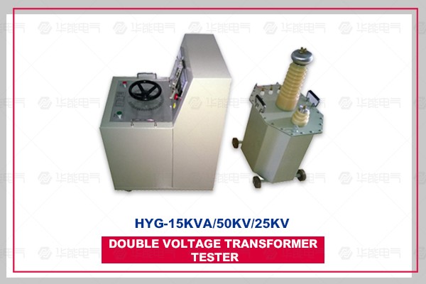
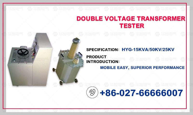
I. Test transformer part
Test transformer, also known as booster, is the basic test equipment for power plants, power supply and distribution systems and scientific research units. It is used to test the insulation strength of various electrical products, electrical components, insulation materials under specified voltage, to check the insulation level of products, to find the insulation defects of the tested products, and to measure the ability of overvoltage.
Working principle
1. AC, AC and DC test transformers:
The power frequency power supply is input into the operating box (or the operating table), and the voltage is adjusted by the voltage regulator from the lotus root to the primary winding of the test transformer. According to the principle of electromagnetic induction, power frequency and high voltage can be obtained in secondary (high voltage) windings. The DC high voltage can be obtained by high voltage silicon stack rectifier and capacitor filter, and its amplitude is 1.4 times of the effective value of AC high voltage. Only the short-circuit pole should be pulled out when using DC and inserted when using AC.
AC Trial Schematic Diagram AC/DC Trial Schematic Diagram
2. Test transformer with tap:
In order to satisfy the contradiction between higher voltage and lower current of a transformer at the same time, the high voltage winding is divided into two windings, one is larger current winding and the other is smaller current winding. Then the two windings are connected in series, respectively. The schematic diagram is as follows:
3. Cascade test transformer:
In order to obtain higher voltage of test transformer, cascade method can also be used to obtain higher voltage. Fig. 2 is the principle wiring diagram of the three-stage series test transformer. The relationship between capacity and voltage of three transformers is satisfied: P1 = 2P2 = 3P3, U (total) = U1 + U2 + U3S.
Cascade trial-change schematic diagram
II. Console Section
This product is the matching equipment of light high voltage test transformer. The shell is welded by cold rolled steel plate. It adopts aluminium alloy sandblasting panel and is equipped with high quality casters. The utility model has the advantages of superior performance, beautiful appearance, firm structure, convenient movement, etc.
Model
Capacity
(KVA)
Power Supply
(V)
Power phase number
Matching Transformer Capacity
(KVA)
Weight
(KG)
HYG-10
Ten
Two hundred and twenty
Three hundred and eighty
One
Two
Ten
Sixty-five
HYG-20
Twenty
Two hundred and twenty
Three hundred and eighty
One
Two
Twenty
Ninety-five
HYG-30
Thirty
Two hundred and twenty
Three hundred and eighty
One
Two
Thirty
One hundred and sixty
HYG-40
Forty
Two hundred and twenty
Three hundred and eighty
One
Two
Forty
One hundred and seventy
HYG-50
Fifty
Three hundred and eighty
Two
Fifty
Two hundred and thirty
When the voltage is over 50 KVA, the induction voltage regulator is used and the voltage regulator is external.